How To Become A Master Systems Integrator – Course

How To Become A Master Systems Integrator – Course

What You Will Learn

Introduction

Learn all about airport systems from the carpark until you are in the air, and Back.

Airports are fun, especially when you walk through and airport and know how everything works. Every airport I go to, when my bag dissapears from the check-in desk, I know where and how it is going to be handled, right up until it is placed on the Aircraft.

I view the Televisions and other displays that shows me where my check-in desk is, where my gate is and what happens when I give my boarding pass to the airline agent at the gate. I know this system, how it works, and where it gets its information from. What a great feeling.

As I travel through the airport I hear automated announcements telling me my flight is ready for boarding, I know this system and how it gets its information and how it is built. The same system can be used in case of an emergency, and I know how this works too.

Mostly going un-noticed is the Closed Circuit Television System. This is where airport security and management can see what is happening both in the Public Areas and Non-public areas. Did you know that if you carry a bag in an airport, set it down and walk away, that automatic sensors within the Closed Circuit Television System can spot this?

If you are travelling internationally you will go through Customs and Immigration. Ever wonder how these systems work? This course will describe these systems.

Did you drive to the Airport and park your car? Did you ever wonder how the Car Park knows how many spaces are available? Did you ever wonder how the entry and exit systems work? This course will tell you how they work.

Airports have elaborate Power and Mechanical Systems that control the temperature, carry you around the terminal using moving walkways, escalators and elevators. Aside from the obvious, do you know why there are moving walkways? They have interesting interfaces and design details which are described in this course.

So, you have travelled through the airport and given your boarding pass to the airline agent, and now you enter the Passenger Loading Bridge. Ever wonder how these devices work? Did you know that in or around the Passenger Loading Bridge there is electrical power provided to the Aircraft? And Air Conditioning?

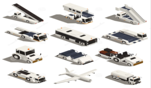
Looking out the window at the Boarding Gate, you see a variety of trucks moving around, some carrying baggage, some catering and some delivering fuel. Sometimes the airport has a fueling system that connects from the ground to the Airplane, ever wonder how the airport charges for the fuel? Take the course and find out.

Finally you are on the aircraft. The pilot tells you they are 3rd in line for take-off, ever wonder who and how this decision is made? Ever wonder what all the lights and paintings are on the taxi-way and runway are used for? Ever wonder what systems are used to help in the management of the taxi-way and runway? The course provides this information too.

You are in the air, ever wonder how the path to the next airport is made? Ever wonder how the aircraft communicates with people on the ground. Every wonder how the aircraft comes in for a landing or takeoff? Yes, this is included in the course.

Well there you have it, from the time you get to the airport until you are in the air, and back again, all of these systems are provided in the course.

Yes, airports can be fun. Even if you are not an Engineer, even passengers can learn about airports.

See you in the course. Enjoy and have fun learning.


BUILDING MANAGEMENT SYSTEM (BMS)

BUILDING MANAGEMENT SYSTEM (BMS)

BUILDING MANAGEMENT SYSTEM (BMS)

This is an excerpt from other BMS specifications. While this specification is one of the better ones for coordinating the BMS with other IT based systems, there are still some problems that need to be addressed.

RELATED DOCUMENTS

Drawings and general provisions of the Contract, including General and Supplementary Conditions and various Divisions Specification Sections, apply to this Section.

SUMMARY

Contractor shall provide all Labor, Materials, Contractor’s Equipment and Plant to fully execute the requirements to furnish, deliver, and install the Works as expressly described in the Drawings and Specification, or implied therefrom, and in accordance with the Contract. It is the intent of this Specification section that the work performed be complete and acceptable in every respect for its intended purpose. It is further required that the provisions of this Specification section shall be complementary to, and shall be correlated with, the requirements of the Contract. Nothing in this specification section shall limit the scope of work as required by the Contract. This last sentence is problematic. No limitations on scope of work! Of what work and what contract. A BMS Contractor will interpret this to mean this Specification (or his subcontract works), but surely not the entire airport! This will require careful consideration, especially in a country where English is not the native language. From the Employers point of view, the Contract is the Whole of the works, and for a main contractor, it is their Contract for their portion of the works. Specifications that contain this kind of language are very dangerous; it could lead to excess bid pricing, omissions in work obligations, and all kinds of problems. Look at all the related works below, this one sentence would make the BMS Contractor responsible for all designs and costs for these interfaces and related works.

RELATED WORKS and INTEGRATION WORKS – See some questions below.

  1. Commissioning
  2. Modular Indoor Central-Station Air-Handling Units
  3. Testing, Adjusting, And Balancing For HVAC (who does this, the BMS Contractor or the Mechanical Contractor?)
  4. Air Duct Accessories
  5. Identification For HVAC Piping And Equipment
  6. Low-Voltage Electrical Power Conductors And Cables
  7. Hangers And Supports For Electrical Systems
  8. Vibration And Seismic Controls For Electrical Systems
  9. Low Voltage Switchgear
  10. Electrical Power Monitoring and Control
  11. Variable-Frequency Motor Controllers
  12. Raceways And Boxes For Electrical Systems
  13. Warranties
  14. Common Work Results For Telecommunications
  15. Telecommunications Horizontal Cabling (who provides the cabling?)
  16. Computer and Server Equipment (who provides the Computer?)
  17. Local Area Network Equipment 
(who provides the LAN?)
  18. Digital Addressable Fire Alarm System


SYSTEM DESCRIPTION

Control system consists of sensors, indicators, actuators, final control elements, interface equipment, other apparatus, and accessories to control mechanical systems.

Control system consists of sensors, indicators, actuators, final control elements; interface equipment, other apparatus, accessories, and software connected to distributed controllers operating in multiuser, multitasking environment on token- passing network and programmed to control mechanical systems.

Control system includes the following interfaces: (who defines the interfaces?)

  1. Air Handling Units (factory and field mounted controls)
  2. Data Center Air Conditioners
  3. Fan Coil Units
  4. Computer room Air Conditioning units
  5. Chilled Water Pumping and Control System
  6. Front-end Workstations and Data and Web servers.
  7. UPS (located for all DDC panels and workstations)
  8. Report Printer
  9. Alarm Printer
  10. VAV / motorised damper terminal boxes. Include all ELV and control wiring, transformers, end switches, test switches as indicated in the typical details.
  11. Miscellaneous Exhaust Systems. 
(How many are there of these miscellaneous exhaust systems? How will the tenderer price for this?)
  12. Interface wiring, conduit, raceways, and relays between fire alarm system devices (shutdown, automatic smoke control and purge overrides) and HVAC equipment (control dampers, AHU VFD’s, etc.). Coordinate shutdown, smoke control and purge override sequence of operations with FAS.
  13. The BMS system shall interface Peer to Peer’ with the Security Management Information System, Security Access Control System and provide alarm information as displayed on the BMS to achieve the sequence of operation.
  14. Provide all wiring from the fire alarm connections (Command and Monitoring Module) and power connection (230V spur) to all fire/smoke and smoke dampers. Include all ELV power and control wiring, transformers, end switches, test switches as indicated in the typical details.
  15. Provide local fire smoke damper control panels (FDCP) in plant rooms and as shown in mechanical plans, wiring in conduit- raceways to all fire smoke dampers for control (power-control wiring and resettable fusible link override) and monitoring (damper end switches) to control panel as shown on drawings.
  16. Coordinate location and quantity of 
 FSD with mechanical drawings and FSD control diagram.
  17. Coordinate locations of command and monitoring modules with the Digital Addressable Fire Alarm Systems contractor based upon the smoke control and purge equipment indicated on drawings.
  18. BMS-Mechanical Power and Control Wiring and raceways for a complete system.
  19. VFD power, control and integration to motors and BMS. 
(Who prepares the Interface Design Document?)
  20. Electric Demand and power Meter Integration to BMS. 
(Who prepares the Interface Design Document?)
  21. Emergency Generator and Fuel Oil System Monitoring and Integration to BMS. 

(Who prepares the Interface Design Document?)
  22. Fire Alarm Integration to BMS. 
(Who prepares the Interface Design Document?)
  23. Lighting Control Integration to BMS. 
(Who prepares the Interface Design Document?)
  24. Server to server integration with the PCA Integration to BMS via Modbus Protocol or OPC protocol. 
(Who prepares the Interface Design Document?)
  25. Server to server integration with the Power Monitoring System (Substations) Integration via Modbus Protocol or OPC protocol. 
(Who prepares the Interface Design Document?)
  26. Server to server integration with passenger conveyance systems for critical alarm and maintenance monitoring only (OPC or Modbus protocol).
  27. Integration with the SCADA power control system via a Modbus protocol. (Who prepares the Interface Design Document?)
  28. Sewage Pit Monitoring. 
(Who prepares the Interface Design Document?)
  29. Grease Pit Alarm Monitoring. 
(Who prepares the Interface Design Document?)
  30. Domestic cold water storage tank monitoring (level alarm) (Who prepares the Interface Design Document?)
.
  31. Irrigation water storage tank monitoring (level alarm). (Who prepares the Interface Design Document?)

I think you get my point about interfaces and making the requirements clear. There are many players involved here, but consider this:

The Employer only sees one main contract. (Of course they may break up the works into a few really big packages)

The Main Contractor has his large package, which may include the Building, MEP Works, and some Special Airport Systems. The Main Contractor will them subcontract these works into 15 or 20 subcontracts.

The Subcontractor will then sub package more works. So by the time you are done, the one main package becomes 100’s of little packages, and guess what? They all now have big GAPS.

Have you done your GAP analysis?

DIGITAL ADDRESSABLE FIRE ALARM SYSTEM

DIGITAL ADDRESSABLE FIRE ALARM SYSTEM

DIGITAL ADDRESSABLE FIRE ALARM SYSTEM

INTERFACES AND GENERAL DESCRIPTION

GENERAL

RELATED DOCUMENTS

Drawings and general provisions of the Contract, including General and Supplementary Conditions and various other Division Specification Sections, apply to this Section.

The related documents section is very critical for the successful interfacing of the Fire Alarm System in an Airport Terminal Building. This excerpt was derived from another airport project and as you may see, there were some interfaces missing. These will be described below.

SUMMARY of WORKS

Contractor shall provide all Labor, Materials, Contractor’s Equipment and Plant to fully execute the requirements to furnish, deliver, and install the Works as expressly described in the Drawings and Specification, or implied therefrom, and in accordance with the Contract. It is the intent of this Specification section that the work performed pursuant hereto be complete and acceptable in every respect for its intended purpose. It is further required that the provisions of this Specification section shall be complementary to, and shall be correlated with, the requirements of the Contract. Nothing in this specification section shall limit the scope of work as required by the Contract.

COMMON RELATED WORK AND INTERFACES (most common)

Note that these interfaces are only defined generally. What will happen if there is a fire and it signals (somehow) the Public Address System? Will an announcement be made? If so, will there be any delay in this announcement to check for a False Alarm? Does both the FAS and PAS have this relationship defined? These definitions are generally in the Interface Design Document (IDD) and should be defined by the Design Engineer and included in the Specifications, prior to Tender. If they are not, get ready for claims. An IDD should be made for every interface, both electronic/IT and Physical.

  1. PUBLIC ADDRESS AND MASS NOTIFICATION SYSTEMS
  2. COMMON WORK RESULTS FOR ELECTRONIC SAFETY AND SECURITY
  3. SECURITY MANAGEMENT INFORMATION SYSTEM
  4. SECURITY ACCESS CONTROL SYSTEM
  5. COMMON WORK RESULTS FOR ELECTRICAL
  6. ENGINE GENERATOR
  7. ELEVATORS
  8. ESCALATORS
  9. MOVING W ALKS
  10. ELECTRIC-DRIVE CENTRIFUGAL FIRE PUMPS
  11. CONTROLLERS FOR FIRE-PUMP DRIVERS
  12. WATER-BASED FIRE SUPPRESSION SYSTEMS
  13. CLEAN-AGENT FIRE EXTINGUISHING SYSTEMS
  14. BUILDING MANAGEMENT SYSTEM
  15. GENERAL FAN REQUIREMENTS
  16. SMOKE CONTROL FANS
  17. AIR CURTAINS
  18. AIR DUCT ACCESSORIES
  19. FIRE SMOKE DAMPERS
  20. MODULAR INDOOR CENTRAL-STATION AIR- HANDLING UNITS
  21. BHS (BAGGAGE HANDLING SYSTEM), Fire Shutters.

The fundamental problem with these interfaces is that they are generally electronic or IT type interfaces. For example, there are no physical interfaces identified. The BHS system will have sensors and water systems installed in and around the conveyors. This will involve at least two contractors (BHS and FAS). So how does the BHS know that someone else will be installing devices on their BHS steelwork? Did somebody check both the BHS and FAS specifications? What will happen if there is damage done to either of the contractor’s works? Sometimes BHS conveyors are attached to the ceiling structure. Can the structure handle the weight and vibration?

Performing a GAP analysis, a specialty of Langholff Digital Solutions, does these types of questions and engineering design works.

SUMMARY (should be more detailed, and make sure these interfaces and devices are properly defined in the subsequent sections of the Specification)

This section of the specifications includes the furnishing, installation, and connection of the fire alarm equipment to form a complete coordinated system ready for operation. It shall include, but not be limited to, alarm initiating devices, alarm notification appliances, control units, fire safety control devices, annunciators, power supplies, display units, workstations, printers, piping and wiring as shown on the drawings and specified.

Main DAFAS Components Includes (Maybe more or less depending on the design):

  1. Fire-alarm control units.
  2. Fire Alarm Terminal Boards (FATB)
  3. Data Gathering Panels (DGP)
  4. Smoke Control system panels (SCSP)
  5. Manual fire-alarm boxes.
  6. System smoke detectors.
  7. Non-system smoke detectors.
  8. Heat detectors.
  9. Notification appliances.
  10. Firefighters’ two-way telephone communication service.
  11. Magnetic door holders.
  12. Remote annunciator.
  13. Addressable interface device.
  14. Air Aspiration Smoke Detection.
  15. Video Smoke and Fire Detection
  16. Digital alarm communicator transmitter.
  17. System printer.
  18. Fire alarm wiring

SYSTEM DESCRIPTION

Note: This section is General and can be used as a reference, not just copy and paste.

  • High speed peer to peer networked Non-coded, digital and fully addressable fire alarm system.
  • System will consist of a collection of Fire Alarm Control Units (nodes), Smoke Management Control panels, Network Control Annunciators (NCA), Network Web Server (NWS), a computer based Color Graphic User Interface shall interface together creating a high speed network system.
  • The Network shall be true peer-to-peer communications architecture. Each node stores its own program and communicates equally with all other nodes.
  • The Network shall be an IP based Ethernet architecture suitable for long range use on fiber optic media or wire media.
  • The Network Control Annunciator and Workstation shall be capable of displaying and controlling all Fire Alarm Control Units on the network.
  • Fire Alarm network shall be (latest version) NFPA Style 7, using fiber optics as the communications media and multiplexed signal transmission, dedicated to fire- alarm service only. The network shall be capable of connecting two nodes separated by XXX Km.
  • The network shall be capable of connecting not less than XXX nodes and expandable to YYY nodes.
  • Fire alarm system with smoke management controls and monitoring status of smoke management components.
  • XXXX (XXX) HDMI LCD YY inch LCD displays (check your IT Master Plan), including gateways and software to manage the fire alarm network communications protocol with the displays. The displays will be located in the Main Fire Command Center, and provide the following displays:
  1. Fire Alarm system status.
  2. Fire Alarm system in alarm
  3. Smoke management system
  4. Video Detection system
  5. Add more as necessary for the actual site condition.

The system shall be capable of providing automatic sensitivity control of smoke detectors.

The system shall include the following sub systems.

  1. Air Aspiration type smoke detection.
  2. Video smoke detection.
  3. Pre action sprinkler system.
  4. Or more depending on the building size and construction
  5. 
 Add more as necessary for the actual site condition.

The Fire Alarm system shall interface Peer to Peer’ with the Security Management Information System, Security Access Control System and provide alarm information as displayed on the fire alarm panel and all other fire alarm information and zone information for unlocking of emergency egress doors in the relevant fire zones to achieve the sequence of operation. 
(This may be different depending on your site condition).


Master Systems Integration – EBOOK

Master Systems Integration – EBOOK

Master Systems Integration - E-Book

A simple (yet complex) tender response for a Master Systems Integration requirement. This E-Book also contains a simple response for MATV and SCADA. This is book 1, and I plan on making more like this for all Airport Systems. You will have to be signed up to this site to get these copies, sorry. You can get a PDF version by clicking this LINK to download the file or you can view a Flip Book HERE.

I hope you Enjoy – Register Now.

Airport Operational Database (AODB)

Airport Operational Database (AODB)

Airport Operational Data Base (AODB) 

The Airport Operational Database (AODB) is the central database where all relevant data will be entered for the processing necessary to manage the operation of the airport. The AODB shall be primarily used for recording of flight movements with the activities and resources required to process the aircraft while at the Main Terminal Building. The AODB System will communicate with other systems through the Information Broker (IB).

  • Interfaces Include (partial):

Building Management System

Common work results for Communications

Communication Rooms Equipment Fittings

Computer and Server Equipment

Local Area Network Equipment

Storage Area Network

Flight Information Display System

Baggage Reconciliation System

Common Use Passenger Processing System

Common Use Self Service System

Local Departure Control System

Travel Document Authorisation System

Information Broker

Resource Management System

Information Kiosk

Baggage Labelling and Tracking System

Public Address and Mass Notification Systems

Clock Systems

Security Access Control System

Baggage Handling System

  • Goals set out in Information Communication Telecommunication (ICT) Strategic Plan
  • Airport Operational Database (AODB) with Information / Message Broker / Service Oriented Architecture (IB/MB/SOA) and Data Warehouse

Various independent existing and planned/future systems at the airport will be integrated using a Service Oriented Architecture (SOA) model, based on an Airport Operation Database (AODB) and Message Broker/Application Server (Middleware) that as a minimum supports data exchange via extensible markup language (XML).

The AODB will serve as a central data repository for all airport related data, including flight schedules, baggage system information, resource allocation and resource usage, collecting data from the various systems to facilitate exchange between them, and storing that data.

The AODB will contain significant amounts of data which can be used for generating historical reports, predicting future needs, analysing operational efficiency, analysing Key Performance Indicators (KPIs), and supporting any number of other management requirements.

The AODB will be at the core of Airport operations and it will drive many critical systems (e.g. Flight and Baggage Information Displays) and it will interface with many other systems (e.g. Financial Systems). The principal aim of the database is to hold this significant amount of data in a single secure location and share the information with systems and applications that require it.

A commercial-off-the-shelf (COTS) database product (such as Oracle) will be used to allow data to be extracted by common report-generating products (such as Crystal Reports), and can be easily accessed via software developed using tools such as the Microsoft .NET series.

At a minimum, the middleware will support message brokering, web services and application services using XML messaging. It will be possible to create interfaces and business process automation using either tool provided by the middleware vendor, or using those provided by third parties.

The AODB is vital for daily operations and it provides information to critical operations systems. It is important not to overload the system with unessential queries for general reporting and analysis purposes. For such cases a data warehousing system would be useful to implement.

The data warehouse should be structured to facilitate timely retrieval of information for reporting purposes. In addition it should support queries from non-critical systems. The data warehouse should also replicate information provided in the AODB as well as be a repository for historical data.

Furthermore, the data warehouse could help facilitate the transition from old software applications to the planned new Enterprise Resource Planning (ERP) solution by sorting and standardising the existing data based on an acceptable and consistent airport wide data dictionary.